Underlay Configuration
This section details the underlay configuration.
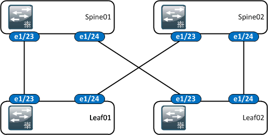
Physical
The physical configuration is in the general leaf/spine format. Within the scope of this scenario we only consider a single leafs. We don't consider how two leafs with a vPC downstream within the scope would integrate with VXLAN + EVPN.

Layer 3
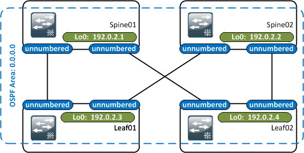
At layer 3, the underlay consists of:
- A single loopback per switch.
- Leaf/spine links are unnumbered, bound to the loopback address.
- OSPF adjacencies are formed across the unnumbered links, distributing the loopback IP addresses.
- All of the layer 3 configuration is within the global routing table.

Loopback Addresses
Loopback IP addresses are assigned out of 192.0.2.0/27, which is a subnet of the the RFC 5737 documentation address space 192.0.2.0/24.
- Spine01 - Lo0: 192.0.2.1/32
- Spine02 - Lo0: 192.0.2.2/32
- Leaf01 - Lo0: 192.0.2.3/32
- Leaf02 - Lo0: 192.0.2.4/32
Point-to-point Links
The point to point links make use of unnumbered links to save on address space. By using unnumbered, number of IPs required is n, where n is the number of switches in the leaf/spine fabric. If we used /31s for the uplinks, we would require n + (2 * 2 * n) or 5n IPs (n loopbacks plus 2 IPs by 2 uplinks by n switches).
The following configuration is applied to the leaf and spine switches:
int ethernet regex 1\/(23|24)
  no switchport
  medium p2p
  ip unnumbered loopback0
  no shutdown
The medium p2p is a config item different between NXOS and IOS. Without this line, the ip unnumbered <interface> command is not available on the interface.
Underlay Unicast Routing
OSPF is used to announce the availability of the loopbacks across the network. The global OSPF configuration is minimal and the same for both spines and leafs: logging adjacency changes and explicitly set the router-ID.
# Spine01 OSPF Global Configuration
router ospf UNDERLAY
  router-id 192.0.2.1
  log-adjacency-changes
The loopback and uplink interfaces are then added to the OSPF process in area 0:
int ethernet regex 1\/(23|24)
  ip router ospf UNDERLAY area 0

interface loopback0
  ip router ospf UNDERLAY area 0
Because of the medium p2p command, we don't need to explicitly call out the OSPF network type, it inherits this:
Leaf01# show ip ospf interface
 ...
 Ethernet1/23 is up, line protocol is up
    ...
    State P2P, Network type P2P, cost 4
At this point, the OSPF neighbours come up and we have each router's type 1 LSA which contains the two uplinks and the loopback:
Spine01# show ip ospf database
        OSPF Router with ID (192.0.2.1) (Process ID UNDERLAY VRF default)

                Router Link States (Area 0.0.0.0)

Link ID         ADV Router      Age        Seq#       Checksum Link Count
192.0.2.1       192.0.2.1       343        0x80000005 0xdb73   3
192.0.2.2       192.0.2.2       345        0x80000009 0xe562   3
192.0.2.3       192.0.2.3       347        0x80000008 0xb990   3
192.0.2.4       192.0.2.4       343        0x80000006 0xcf79   3
The loopbacks are now visible as OSPF routes in the global routing table:
Leaf01# show ip route ospf-UNDERLAY

192.0.2.1/32, ubest/mbest: 1/0
    *via 192.0.2.1, Eth1/23, [110/5], 00:09:14, ospf-UNDERLAY, intra
192.0.2.2/32, ubest/mbest: 1/0
    *via 192.0.2.2, Eth1/24, [110/5], 00:09:14, ospf-UNDERLAY, intra
192.0.2.4/32, ubest/mbest: 2/0
    *via 192.0.2.1, Eth1/23, [110/9], 00:09:08, ospf-UNDERLAY, intra
    *via 192.0.2.2, Eth1/24, [110/9], 00:09:08, ospf-UNDERLAY, intra
These loopbacks will serve as both the source/destination for the iBGP sessions to the spine switches, as well as the VTEPs.
Underlay Multicast Routing
Multicast routing will be used to replicate broadcast/unknown unicast/multicast (BUM) overlay traffic to multiple VTEPs.
We will use an anycast rendezvous point (RP), with the spines acting as RPs. However we won't be using MSDP to distribute multicast information between the spines, but will be using the Nexus specific anycast-rp configuration.
We create a new loopback interface on Spine01 and Spine02 which is assigned the anycast IP address. We take the IP address from the top of our loopback space:
interface loopback1
  ip address 192.0.2.255/32
The PIM feature is enabled on the switches, and sparse mode on all of our interfaces. The spine configuration is:
feature pim

int ethernet regex 1\/(23|24)
  ip pim sparse-mode

interface loopback0
  ip pim sparse-mode

interface loopback1
  ip pim sparse-mode
The leaf configuration is:
feature pim

int ethernet regex 1\/(23|24)
  ip pim sparse-mode

interface loopback0
  ip pim sparse-mode